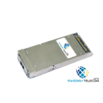
Description
- 100Gb/s transceiver module for optical communication applications compliant to 100GBASE-LR4 of the IEEE P802.3ba standard. The module converts 4 input channels of 25Gb/s electrical data to 4 channels of LAN WDM optical signals and then multiplexes them into a single channel for 100Gb/s optical transmission. Reversely on the receiver side, the module de-multiplexes a 100Gb/s optical input into 4 channels of LAN WDM optical signals and then converts them to 4 output channels of electrical data.The central wavelengths of the 4 LAN WDM channels are 1295.56, 1300.05, 1304.58 and 1309.14 nm as members of the LAN WDM wavelength grid defined in IEEE 802.3ba. The high performance cooled LAN WDM EA-DFB transmitters and high sensitivity PIN receivers provide superior performance for 100Gigabit Ethernet applications up to 10km links and compliant to optical interface with IEEE802.3ba Clause 88 100GBASE-LR4 requirements.
The product is designed with form factor, optical/electrical connection and MDIO interface according to the CFP4 Multi-Source Agreement (MSA). The innovative design has all the fibers inside the CFP4 package configured without any splicing or non-permanent connector. Also, fiber routines are neatly organized and fixed inside a stainless steel container.
This product contains a duplex LC connector for the optical interface and a 56-pin connector for the electrical interface. Figure 1 in Section 3 shows the functional block diagram of this product.
Receiver Operation
The receiver receives 4-lane LAN WDM optical signals. The optical signals are de-multiplexed by a 1-to-4 optical DEMUX and each of the resulting 4 channels of optical signals is fed into one of the 4 receivers that are packaged into the Receiver Optical Sub-Assembly (ROSA). Each receiver converts the optical signal to an electrical signal. The regenerated electrical signals are retimed and de-jittered and amplified by the RX portion of the 4-channel CDR. The retimed 4-lane output electrical signals are compliant with IEEE CAUI-4 interface requirements. In addition, each received optical signal is monitored by the DOM section. The monitored value is reported through the MDIO section. If one or more received optical signal is weaker than the threshold level, RX_LOS hardware alarm will be triggered.
MDIO Interface
The CFP4 module supports the MDIO interface specified in IEEE802.3ba Clause 45. It supports alarm, control and monitor functions via hardware pins and via an MDIO bus. Upon module initialization, these functions are available. CFP4 MDIO electrical interface consists of 6 wires including 2 wires of MDC and MDIO, as well as 3 Port Address wires, and the Global Alarm wire. MDC is the MDIO Clock line driven by host and MDIO is the bidirectional data line driven by both host and module depending upon the data directions. The CFP4 uses pins in the electrical connector to instantiate the MDIO interface as listed in Table 1. MDIO Interface Pins.
-
- Hot pluggable CFP4 MSA form factor
- Compliant to IEEE 802.3ba 100GBASE-LR4 and CFP-MSA-CFP4-HWac-Specification
- Transmitter: cooled 4x25Gb/s LAN WDM EML TOSA (1295.56, 1300.05, 1304.58, 1309.14nm)
- Receiver: 4x25Gb/s PIN ROSA
- 4x28G Electrical Serial Interface (CEI-28G-VSR)
- MDIO management interface with digital diagnostic monitoring
- Up to 10km reach for G.652 SMF
- Duplex LC receptacle
- Single +3.3V power supply
- Power consumption less than 5.5W
- Operating case temperature: 0~70oC
- RoHS-6 compliant
- 100GBASE-LR4 Ethernet
- OTN OTU4


